
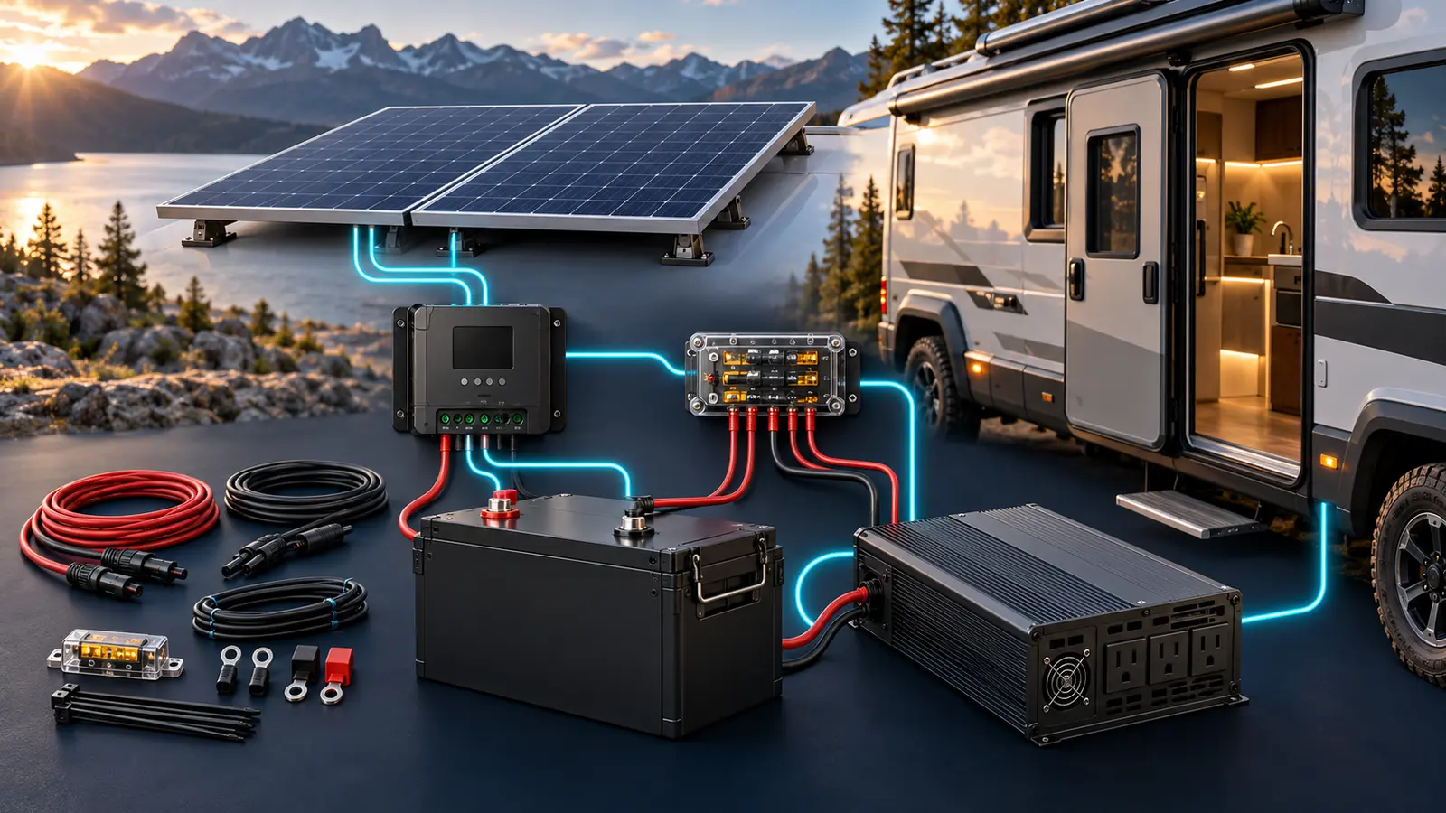
An RV solar panel kit with battery and inverter can simplify shopping, but a “complete kit” is complete only for a defined load and installation. A bundle may include panels, controller, battery, inverter, brackets, and cables while still omitting roof sealant, cable entry, busbars, disconnects, branch protection, battery restraint, shore charging, alternator charging, or model-specific adapters.
The safe way to choose a kit is to design the energy system first, then decide whether a bundle covers it. Start with watt-hours per day, maximum simultaneous AC watts, days of storage, solar conditions, and other charging sources. Finally, audit every component and protection device.
What a complete RV solar system includes
| Function | Component | What to verify |
|---|---|---|
| Collect sunlight | Solar panels | Array watts, Voc, Isc, roof area, mounting |
| Convert solar power | MPPT or PWM controller | PV voltage/current, output current, battery profile |
| Store energy | Battery bank | Wh, chemistry, charge/discharge limits, cold behavior |
| Convert DC to AC | Pure sine wave inverter | Continuous watts, surge, idle draw, transfer function |
| Distribute DC | Busbars and fuse panel | Current and fault ratings, covers, branch capacity |
| Protect conductors | Fuses/breakers | DC voltage and interrupting ratings, correct placement |
| Isolate system | Disconnects | DC rating, load-breaking ability, accessibility |
| Monitor energy | Shunt/monitor | All current paths measured, battery compatibility |
| Recharge elsewhere | Shore and alternator chargers | Profiles, current limits, control, isolation |
| Install physically | Cable, lugs, glands, mounts | Size, insulation, weather seal, strain relief, torque |
If a listing does not specify the protection and installation hardware, assume more design work is needed.
Step 1: Build a daily energy budget
| RV load | Example watts | Daily use | Energy |
|---|---|---|---|
| 12V refrigerator | 45W running | 8 equivalent hours | 360Wh |
| Roof fan | 18W | 6 hours | 108Wh |
| LED lighting | 20W | 4 hours | 80Wh |
| Laptop and monitor | 100W | 3 hours | 300Wh |
| Phones and small devices | — | — | 80Wh |
| Water pump and controls | — | — | 40Wh |
| Inverter standby and conversion | — | — | 90Wh |
| Illustrative total | 1,058Wh/day |
Add a planning allowance. At 15%, the example becomes about 1,217Wh/day. Real refrigerator energy changes with ambient temperature and ventilation; inverter standby can range widely. Measure actual loads if possible.
Heating water, warming air, and cooking with electricity dominate small RV systems. A 1,500W appliance running for 30 minutes consumes 750Wh before inverter loss—most of the daily budget above.
Step 2: Size the battery bank
A planning formula is:
Battery Wh = daily load Wh x days of autonomy / usable planning factor
For 1,217Wh/day, 1.5 days, and an illustrative 0.85 usable factor:
1,217 x 1.5 / 0.85 = about 2,148Wh
At 12.8V, that is roughly:
2,148Wh / 12.8V = 168Ah
A 200Ah LFP bank is a sensible design candidate. It does not guarantee success: the BMS must also supply inverter current and accept combined charge current.
For lead-acid, the usable planning factor and voltage behavior differ. Do not size lithium and lead-acid banks from nameplate amp-hours as if they were identical.
Step 3: Size the solar array
Use:
Solar watts = daily Wh / (peak-sun-hours x system factor)
For 1,217Wh/day, four peak-sun-hours, and a 0.75 factor:
1,217 / (4 x 0.75) = about 406W
A nominal 400W array is the minimum mathematical result for the assumed day. It has little margin for shade, roof heat, clouds, low winter sun, or battery recovery after a poor day. If roof space and controller capacity allow, more array or another charging source improves resilience.
Peak-sun-hours are not daylight hours. One peak-sun-hour is an equivalent hour at 1,000W/m² solar irradiance. Use location- and season-appropriate data rather than a single national average.
Step 4: Choose the charge controller
MPPT controllers usually offer more design flexibility and energy harvest than simple PWM controllers, particularly with higher-voltage arrays and changing conditions. The controller must pass two independent checks.
PV input side
- Cold-adjusted array Voc below the absolute maximum
- Operating Vmp inside the MPPT range
- Array current and short-circuit current within permitted limits
- Series/parallel arrangement and branch protection approved
Battery output side
Controller current is roughly solar watts divided by charging voltage, adjusted for efficiency. A 400W array charging near 14V can approach 29A under strong conditions. A 40A controller gives reasonable headroom; final sizing follows the controller’s own method.
Program the correct battery profile. Disable lead-acid equalization unless the lithium battery maker explicitly calls for a comparable function, which is uncommon.
Step 5: Size the inverter from loads, not battery watt-hours
List appliances that can operate together and their startup surge.
| Appliance | Example running watts | Design note |
|---|---|---|
| Laptop and monitor | 100W | Often more efficient via USB-C/DC |
| Microwave | 1,200W input | Nameplate cooking watts can be lower than electrical input |
| Induction cooktop | 1,300W | High daily energy use |
| Refrigerator | 50W | Compressor startup matters |
| Coffee grinder | 200W | Short duration |
If a 1,300W cooktop and 100W work setup may run together, a 1,500W inverter has little margin. A 2,000W pure sine inverter may be appropriate, but it can draw about 185A from a 12V battery at full load using a 90% efficiency assumption and 12V under load.
The battery BMS, main fuse, disconnect, busbars, and cables must support that current. An oversized inverter does not create more battery energy; it can encourage loads that empty the bank quickly and consumes standby power.
Step 6: Decide between 12V and 24V
A 12V system is common in RVs and works well for modest loads. At higher inverter power, current becomes difficult:
- 2,000W at 12V and 90% efficiency: about 185A
- 2,000W at 24V and 90% efficiency: about 93A
Lower current reduces cable size and voltage-drop pressure. A 24V bank needs a compatible inverter, chargers, protection, and a DC-to-DC converter for 12V loads. Do not mix nominal voltages without a deliberate architecture.
What commercial kits actually provide
Renogy currently publishes 400W off-grid and RV kits, including bundles with panels and controllers and a separate complete-kit listing with battery options. These pages are useful for understanding bundle structure, not proof that a kit fits every RV.
Audit the product list line by line:
- Are panel mounting feet included and suitable for the roof?
- Does the cable length match the actual route?
- Is the controller compatible with the array configuration?
- Is the battery the selected chemistry and capacity?
- Is the inverter pure sine wave and appropriately rated?
- Are battery-to-inverter cables and a model-specific fuse included?
- Are busbars, disconnects, branch fuses, and shunt included?
- Does the kit support alternator or shore charging?
A kit with a PWM controller may be economical for a simple small array. An MPPT system is usually more adaptable for a serious RV installation.
Three example system classes
Weekend 200W / 100Ah system
Suitable for lights, fan, devices, and a careful refrigerator budget when driving or shore power is frequent.
- 200W solar
- 100Ah LFP, about 1.28kWh nameplate
- 20–30A controller, subject to array design
- 500–1,000W inverter only if loads and BMS support it
- DC-to-DC or shore charging for recovery
This is not an all-electric kitchen system.
Balanced 400W / 200Ah system
A common candidate for extended van or RV use.
- 400W roof array
- 200Ah LFP, about 2.56kWh nameplate
- Approximately 40A MPPT, after exact calculation
- 1,500–2,000W pure sine inverter if bank current allows
- 30–50A alternator charger, vehicle-dependent
- Lithium-compatible shore charger
This can support a refrigerator, ventilation, remote work, and brief high-power appliances with deliberate use.
High-demand 800W / 400Ah system
For larger RVs, heavier work loads, and more electric cooking.
- 800W array, roof space permitting
- 400Ah LFP at 12V or a 24V architecture
- Controller(s) sized for array voltage/current and redundancy goals
- 2,000–3,000W inverter/charger
- Engineered alternator and shore charging
- Higher-current busbars, fusing, distribution, and monitoring
At this scale, professional system design is strongly recommended.
Roof planning
Measure usable roof area around vents, air conditioners, antennas, racks, shadows, and required service clearances. A dimensioned roof plan should show each panel and mounting foot.
Consider:
- Panel access for inspection and removal
- Shade from vents and roof equipment throughout the day
- Wind loading and manufacturer-approved mounts
- Roof structure and leak-resistant penetrations
- Cable entry with drip loop, gland, strain relief, and sealant compatible with roof material
- Junction and disconnect accessibility
Do not drill until the interior route and roof structure are known.
Protection and distribution
At minimum, the final design may include:
- Battery main fuse
- Battery disconnect
- Covered positive and negative busbars
- Shunt and battery monitor
- Solar-controller battery-side protection
- PV disconnect and string protection where required
- Alternator charger protection at both energy sources
- Inverter fuse and disconnect as specified
- DC distribution-panel feeder protection
- Individual branch fuses
- Shore inlet and AC main/branch protection
Fuse placement follows energy sources. A conductor connecting two batteries can require protection at both ends.
Kit audit: make a missing-parts budget
The advertised bundle price can hide a large second order. Create a spreadsheet with one row for every component and mark it included, unsuitable, or still required.
Typical omissions include:
- Roof-compatible mounting hardware and approved sealant
- Weatherproof cable gland and strain relief
- Longer PV cable or correctly rated rooftop connectors
- Main battery fuse, holder, disconnect, and covers
- Inverter fuse and cables sized for the actual route
- Positive and negative busbars
- Battery monitor and shunt
- DC fuse panel and spare fuses
- Cable lugs, heat-shrink, labels, and abrasion protection
- Grounding and AC-distribution hardware
- Battery restraint or heated enclosure
- DC-to-DC alternator charger and both source fuses
A bundle that costs less but requires replacement of its controller, inverter cables, and roof brackets is not the lower-cost system. Include installation tools, professional review, shipping, and service access in the comparison.
Expandability and upgrade paths
Before committing to a kit, ask what happens when the owner adds a second battery, another 200W of solar, or a larger inverter. The original controller may have no PV voltage or output-current headroom. The supplied busbars and disconnect may be near their limit. A small battery monitor may not support the new architecture.
Designing one practical expansion step into the original system can avoid rewiring the entire RV. Leave physical space, choose busbars and conduit deliberately, and document spare controller and fuse-panel capacity. Do not oversize protection for future wire that has not been installed.
Commission the system before relying on it
An installation is not finished when the display first lights up. Energize one source and one load group at a time. Confirm polarity, charger settings, shunt direction, battery temperature data, and protective-device ratings before applying a large inverter load.
Under controlled operation, record battery voltage, controller output, cable drop, connection temperature, and inverter behavior. Compare the results with the manuals. Test shore transfer and charging separately from inverter mode. Verify that every disconnect actually isolates the circuits shown on its label and that solar or alternator feeds do not unexpectedly keep a bus energized.
Store the final wiring diagram, torque values, fuse list, model numbers, and programming settings in the RV. A documented baseline makes later troubleshooting safer and reveals whether a connection or battery has changed over time.
Alternator charging
Solar-only kits can struggle during winter, forest camping, or several cloudy days. A DC-to-DC charger can provide predictable energy while driving and protect a smart alternator strategy.
Confirm:
- Alternator output available at idle and cruising speed
- Existing vehicle electrical load
- Charger input draw, which exceeds output after loss
- Source and house-side fusing
- Ignition/engine-run control
- Cable length and voltage drop
- Battery charge-current limit when solar and shore charging are also active
Do not select the charger merely because the battery can accept its headline amps.
Shore power and inverter/charger decisions
A combined inverter/charger can charge the battery, supply AC loads, and switch between shore and inverter modes. This reduces box count but introduces AC transfer, neutral-ground bonding, current limits, and programming responsibilities.
A separate inverter and converter can be simpler to service. Whichever architecture is chosen, never backfeed an RV receptacle through a male-to-male cord. Use listed transfer and distribution equipment installed to applicable standards.
Installation mistakes that make a good kit fail
- Solar array voltage exceeds the controller’s cold-weather limit
- Inverter cables are sized from average load instead of maximum current
- Controller and charger negatives bypass the shunt
- Battery is not secured for vehicle movement
- Main fuse is far from the battery
- Cable is routed through metal without abrasion protection
- Multiple batteries use unequal interconnect paths
- Roof panels are placed in permanent vent shadow
- Lithium charging continues below the battery’s permitted temperature
- Inverter ventilation is blocked by bedding or cargo
- AC output and shore power lack an approved transfer arrangement
Buying checklist
- Complete a 24-hour energy audit.
- Calculate maximum simultaneous AC watts and surge.
- Choose storage days and battery chemistry.
- Size solar from local seasonal sun and recovery needs.
- Check array Voc, current, wattage, and controller output.
- Decide 12V versus 24V architecture.
- Audit every bundle component and omitted part.
- Add alternator and shore charging where needed.
- Design conductor sizing, fusing, disconnects, busbars, and monitoring.
- Draw the physical roof and electrical layouts.
- Review equipment manuals and applicable RV standards.
- Have the final high-current and AC design professionally reviewed.
Frequently asked questions
What size solar kit does an RV need?
It depends on daily watt-hours and local sun. A 200W kit can cover light weekend loads; 400W is a common candidate for a refrigerator and remote work; larger or all-electric loads may need 800W or more plus alternator/shore charging.
Does an RV solar kit need an inverter?
Only for AC appliances. Native 12V or USB-C devices can run without it and may use less energy. Size an inverter from the simultaneous AC loads.
Is a 100Ah lithium battery enough with 400W solar?
It may be enough when daily consumption is modest and sun is reliable. The array can recharge quickly, but the battery still determines overnight storage and inverter-current capability.
Can a solar kit charge while driving?
Roof solar can charge while driving if the system is designed for it. Alternator charging is a separate branch and usually needs a compatible DC-to-DC charger.
Are complete kits easier to install?
They reduce component selection but do not remove the need for load calculations, roof work, cable routing, protection, configuration, and code compliance.
Bottom line
Choose an RV solar panel kit with battery and inverter only after calculating the system it must become. For many extended-travel rigs, a balanced starting point is around 400W solar, 200Ah LFP, and a 1,500–2,000W pure sine inverter, backed by alternator or shore charging. That is a design example, not a universal prescription.
A bundle is valuable when its panel, controller, battery, inverter, protection, cabling, and documentation genuinely fit the same plan. Otherwise, individually selected components can produce a safer and more useful system.
Keep room in the plan for maintenance access, replacement parts, and future inspection.
Label every cable clearly.
Sources
- Renogy 400W general off-grid solar kit: https://www.renogy.com/products/renogy-400w-12v-general-off-grid-solar-kit
- Renogy 400W RV solar kit: https://www.renogy.com/products/renogy-400w-12v-solar-rv-kit
- Renogy 400W complete kit with batteries: https://www.renogy.com/products/400w-12-volt-complete-solar-kit-with-two-100ah-deep-cycle-agm-lifepo4-batteries
- Renogy charge-controller sizing guide: https://www.renogy.com/blogs/buyers-guide/solar-charge-controller-sizing-and-how-to-choose-one
- Renogy series and parallel guide: https://www.renogy.com/blogs/learn-center/learn-series-and-parallel
- US Department of Energy PV performance guide: https://www.energy.gov/sites/default/files/2022-02/understanding-solar-photo-voltaic-system-performance.pdf
- Victron Energy, Wiring Unlimited: https://www.victronenergy.com/upload/documents/Wiring-Unlimited-EN.pdf
- NFPA 1192 overview: https://www.nfpa.org/codes-and-standards/nfpa-1192-standard-development/1192
Related guides: RV solar kit basics and complete van electrical planning.