
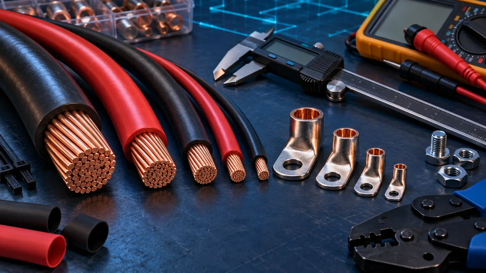
A wire gauge calculator is a good first filter for a 12V circuit, but it cannot see how the cable is installed. It does not know whether the wire runs through insulation, shares a hot bundle, enters an engine compartment, uses 105°C marine cable, or terminates on a device that accepts only a certain size.
The safe method is to check both sides of the problem:
- Voltage drop: Is the conductor large enough to deliver adequate voltage at the load?
- Ampacity and protection: Can the installed conductor carry the current safely, and will the fuse protect the smallest conductor and connected equipment?
Use the larger wire size produced by those checks, then confirm it against the equipment manual and applicable RV or vehicle standard.
Inputs a useful calculator needs
| Input | What to enter | Why it matters |
|---|---|---|
| System voltage | 12V, 12.8V, 24V, etc. | The same voltage loss is a larger percentage in a low-voltage system |
| Load current | Expected maximum continuous amps | Determines heating and voltage drop |
| Circuit length | Positive out plus negative return, unless tool says one-way | Resistance exists in the complete path |
| Allowed voltage drop | Often 3% for sensitive/critical loads, 10% for some noncritical loads | Lower allowance requires larger wire |
| Conductor material | Copper or aluminum | Resistivity differs |
| Temperature/installation | Insulation rating, bundle, engine space, ambient | Changes safe ampacity |
| Protection | Fuse/breaker type and rating | Must protect the conductor and interrupt the DC fault |
Blue Sea Systems’ Circuit Wizard is a useful external cross-check because it asks for voltage, load current, conductor length, allowable voltage drop, load type, insulation temperature, and whether the conductor is in an engine room. That is more informative than a chart labeled only “amps versus AWG.”
The voltage-drop formula
For a copper two-conductor DC circuit, a planning equation is:
Voltage drop = current x circuit resistance
Circuit resistance can be estimated from conductor resistance per unit length:
Voltage drop = amps x total circuit feet x ohms per foot
Percentage drop is:
Voltage-drop % = voltage drop / system voltage x 100
If a calculator asks for one-way distance, it may double it internally. If it asks for total conductor length, enter the full positive-plus-negative path. Read the field label; entering one-way length in a calculator expecting circuit length can understate drop by half.
Worked example: refrigerator circuit
Assume:
- Maximum current: 6A
- One-way distance: 15 ft
- Total circuit length: 30 ft
- System voltage: 12V
- Target drop: 3% or less
The maximum drop is:
12V x 0.03 = 0.36V
The maximum total circuit resistance is:
0.36V / 6A = 0.06 ohm
Divide by 30 ft:
0.06 / 30 = 0.002 ohm per foot maximum
Choose a copper conductor whose documented resistance is below that value, then check ampacity, temperature derating, terminal compatibility, and the refrigerator manual. A larger wire can be justified because compressor startup and low battery voltage make drop more consequential.
Worked example: roof fan
Assume a 3A fan, 12 ft one-way, and 3% target:
- Total path: 24 ft
- Allowed drop: 0.36V
- Maximum circuit resistance: 0.36 / 3 = 0.12 ohm
- Maximum resistance per foot: 0.12 / 24 = 0.005 ohm/ft
Voltage drop may select a relatively small conductor, but the final choice must still meet minimum mechanical size, appliance instructions, fuse-terminal range, and installation rules. Very small wire is easier to damage and may not crimp reliably in some RV hardware.
Worked example: 1,000W inverter
High-power inverter circuits expose why generic 12V charts are dangerous.
At 1,000W AC, 12V at the battery, and 90% assumed efficiency:
DC current = 1,000 / (12 x 0.90) = about 93A
At low battery voltage or during surge, current can be higher. Cable length, battery-bank capability, inverter terminal size, and fuse class become critical. Use the inverter manufacturer’s exact cable and fuse table.
For example, Victron’s Inverter Smart installation documentation lists model-specific cable cross-section, external fuse rating, and battery capacity. Samlex inverter manuals provide their own tables. A general calculator is not a substitute for those values.
Why 12V systems need large conductors
Power equals voltage multiplied by current:
Watts = volts x amps
Delivering 1,200W ideally requires 100A at 12V but only 50A at 24V. For the same conductor resistance, heat loss is proportional to current squared:
Cable loss = current² x resistance
Doubling current can create four times the cable heating for the same resistance. That is why a 12V inverter bank quickly needs large cables and why a 24V architecture may be more practical for higher power.
Voltage drop targets
There is no single percentage for every RV circuit. The equipment manual and applicable standard control the final value. As a planning convention:
| Circuit type | Common planning target | Why |
|---|---|---|
| Electronics, refrigerator, charging sense | Around 3% | Voltage-sensitive behavior and compressor startup |
| General lighting | 3–5% | Brightness and long-run efficiency |
| Short intermittent loads | Project-specific | Duty cycle and startup still matter |
| Inverter battery cable | Follow exact manual; minimize drop | Low voltage causes high current and inverter shutdown |
Do not use a permissive 10% target merely to make a smaller wire appear acceptable. A 10% drop on a nominal 12V circuit is 1.2V, which can cause some devices to shut down or draw more current.
Ampacity is not the same as voltage drop
A conductor can be cool enough yet deliver too little voltage over a long run. It can also meet voltage-drop math yet be unsafe because high ambient temperature, bundling, insulation rating, or terminal limits reduce allowable current.
Check:
- Conductor insulation temperature rating
- Ambient temperature
- Number of current-carrying conductors in a bundle
- Engine-compartment or other hot location
- Conduit, insulation, and airflow
- Flexible strand construction and listed application
- Terminal and device temperature rating
- Continuous versus intermittent duty
Use tables from the applicable standard or cable manufacturer, not a random infographic without test conditions.
The fuse protects the wire
A branch fuse is selected so that a fault opens the circuit before the protected conductor is damaged. It also has to tolerate the load’s normal current and startup behavior.
The fuse rating must not exceed the allowable ampacity of the smallest conductor in the protected path. If a short 4 AWG feeder transitions to 10 AWG downstream without new protection, the upstream fuse must protect the 10 AWG section or a correctly rated branch device must be added.
The fuse also needs:
- A DC voltage rating at or above system maximum
- Adequate interrupting capacity for the available battery fault current
- A time-current characteristic suited to the load
- Listed holder, temperature rating, and secure terminal connections
Littelfuse emphasizes matching fuse protection to wire gauge and insulation so overloads and short circuits do not damage the conductor.
Source-side protection
A wire connected between two energy sources can need protection at both ends. A DC-to-DC charger cable, for example, can be energized by the starter battery on one side and the house battery on the other. Each end’s fuse protects the conductor from that source.
A solar controller’s battery cable is also connected to a battery capable of high fault current even when the controller is off. Do not assume the controller’s current limit protects a shorted battery cable.
AWG versus mm²
American Wire Gauge numbers become smaller as conductors become larger. Metric cable is labeled by conductor cross-sectional area in square millimeters. Approximate conversion charts can be misleading because a nearby metric size may be smaller than the AWG conductor and insulation systems differ.
Do not relabel a conductor from overall cable diameter. Read the manufacturer’s conductor area and construction. When a device terminal lists an allowed range, use a size, ferrule or lug, and crimp method accepted by that terminal.
Flexible battery cable and fine-stranded wire
Vehicle systems need cable that tolerates vibration and routing. Fine-stranded cable is flexible, but its outside diameter and required lug can differ from building wire of the same nominal gauge. Use terminals listed or specified for the strand class.
Never remove strands to fit an undersized lug. Never fill a loose terminal with solder. A correct crimp forms a gas-tight mechanical connection with approved tooling; heat-shrink provides strain relief and insulation but does not rescue a poor crimp.
Calculator workflow
- Record the appliance’s maximum current and startup behavior.
- Measure the actual one-way cable route, including bends.
- Decide the allowed voltage drop from the manual and design.
- Run the voltage-drop calculation.
- Check ampacity under the real installation conditions.
- Choose the larger conductor required by either check.
- Confirm the device terminal accepts that size.
- Select protection that safeguards the smallest conductor.
- Confirm fuse voltage and interrupting ratings.
- Document the result on the wiring diagram.
- After installation, measure loaded voltage at source and load.
Practical circuit worksheet
| Field | Entry |
|---|---|
| Circuit name | |
| Nominal and minimum design voltage | |
| Continuous current | |
| Startup/surge current and duration | |
| One-way route length | |
| Total circuit length used by calculator | |
| Allowed voltage drop | |
| Calculator result | |
| Ampacity/derating result | |
| Selected conductor and insulation | |
| Fuse/breaker type and rating | |
| Terminal/lug and torque | |
| Measured loaded drop |
Keeping this worksheet with the van’s diagram makes future troubleshooting much faster.
Validate the installed circuit with measurements
A calculation should be followed by a controlled loaded test. Measure voltage at the battery or distribution source and again at the appliance while it is operating near its expected maximum. The difference is the total drop across positive and negative paths.
If the source reads 12.6V and the load reads 12.1V:
Drop = 12.6 – 12.1 = 0.5V
Drop percentage = 0.5 / 12.6 x 100 = 4.0%
A higher-than-planned result can come from an undersized cable, longer actual route, poor crimp, loose terminal, weak fuse holder, corroded connector, or unexpected current. Measure individual segments to localize the loss. A thermal camera or contact-temperature measurement used safely under known load can help identify a hot high-resistance connection, but temperature alone does not prove the circuit is correctly sized.
Stop the test if insulation, terminals, holders, or equipment become abnormally hot, voltage becomes unstable, or protective devices operate. De-energize before tightening or disassembling connections.
Voltage drop changes with system voltage
A 0.5V loss is about 4.2% of 12V but only about 2.1% of 24V. That is one reason higher-voltage architectures are attractive for long or high-power circuits. The conductor still needs ampacity and protection checks; raising voltage does not make an undersized cable safe.
For an appliance designed only for 12V, a 24V bank requires a correctly sized DC-to-DC converter. Size both converter input and output circuits because their currents differ.
Do not “solve” a measured drop by installing a larger fuse. A higher fuse rating does not reduce resistance and can leave the conductor less protected. Correct the cable size, termination, route, or damaged hardware, then repeat the controlled load test.
Common wire-sizing mistakes
- Entering one-way distance into a tool that expects total circuit length
- Using appliance average current instead of maximum running current
- Ignoring motor/compressor startup
- Selecting wire from voltage drop without checking ampacity
- Selecting a fuse from appliance watts rather than conductor protection
- Treating chassis metal as a zero-resistance return path
- Ignoring hot, bundled, or insulated routing
- Using a wire size the equipment terminal cannot accept
- Extending a factory inverter cable without recalculating the entire path
- Assuming a BMS current limit replaces a fuse
Frequently asked questions
What wire gauge do I need for 12V?
There is no answer without current, route length, allowed voltage drop, conductor type, ambient temperature, bundling, and protection. Enter those values in a reputable calculator, then verify ampacity and the equipment manual.
Is the circuit length one way or round trip?
Voltage drop occurs in both positive and negative conductors. Some calculators request one-way distance and double it internally; others request total circuit length. Follow the tool’s label.
Can I use a larger wire than the calculator suggests?
Usually, if the terminals, lugs, bend radius, fuse, and installation support it. Larger wire reduces drop. Do not force an oversized conductor into a terminal or trim strands.
Does a fuse protect the appliance or the wire?
Its primary circuit role is to protect the conductor from overcurrent, while equipment may also specify protection for internal faults or warranty compliance. The final rating must satisfy both without exceeding conductor limits.
Why does another calculator give a different result?
It may use one-way versus total length, different copper resistance, temperature assumptions, voltage-drop targets, ampacity tables, or rounding. Compare inputs and methods, then use the more conservative result that satisfies the governing documentation.
Bottom line
Use a wire gauge calculator to estimate voltage drop, not to outsource the electrical design. The final conductor must pass voltage-drop and ampacity checks, fit its terminals, survive the installation environment, and be protected by a correctly rated fuse or breaker.
For high-current battery, alternator, and inverter circuits, follow the exact equipment tables and have the design reviewed by a qualified RV electrical professional.
Save the final calculator inputs, not only its answer, because a later owner needs to know the assumed current, length, temperature, and drop target.
Keep revision dates too.
Sources
- Blue Sea Systems Circuit Wizard: https://circuitwizard.bluesea.com/
- Blue Sea Systems, Choosing the Correct Wire Size: https://www.bluesea.com/articles/1437
- Victron Energy, Wiring Unlimited: https://www.victronenergy.com/upload/documents/Wiring-Unlimited-EN.pdf
- Victron Inverter Smart installation: https://www.victronenergy.com/media/pg/Inverter_Smart/en/installation.html
- Samlex inverter manuals and specifications: https://samlexamerica.com/resources-support/product-documentation/
- Littelfuse Fuseology: https://www.littelfuse.com/assetdocs/littelfuse-fuseology?assetguid=c81c1a21-b903-44b6-b46d-180c48f7c3c5
- NFPA 1192 overview: https://www.nfpa.org/codes-and-standards/nfpa-1192-standard-development/1192
Related guides: van electrical system guide and camper wiring diagram explanation.