
A van wiring diagram looks like a plate of spaghetti until you stop reading it as one big drawing. It’s really a handful of short paths. Power comes in from somewhere (solar, the alternator or a campground plug), gets sorted by a charger or controller, lands in the house battery, and then leaves through fuses to whatever you want to run.
This page walks through those paths one at a time. It’s a map for understanding, not a build sheet. It won’t tell you which wire gauge or fuse to buy, because that depends on your exact gear. For starting numbers, use our wire gauge calculator and fuse sizing calculator, then check the result against your equipment’s manuals. If you’re brand new to all this, read the beginner’s guide to van electrical systems first.
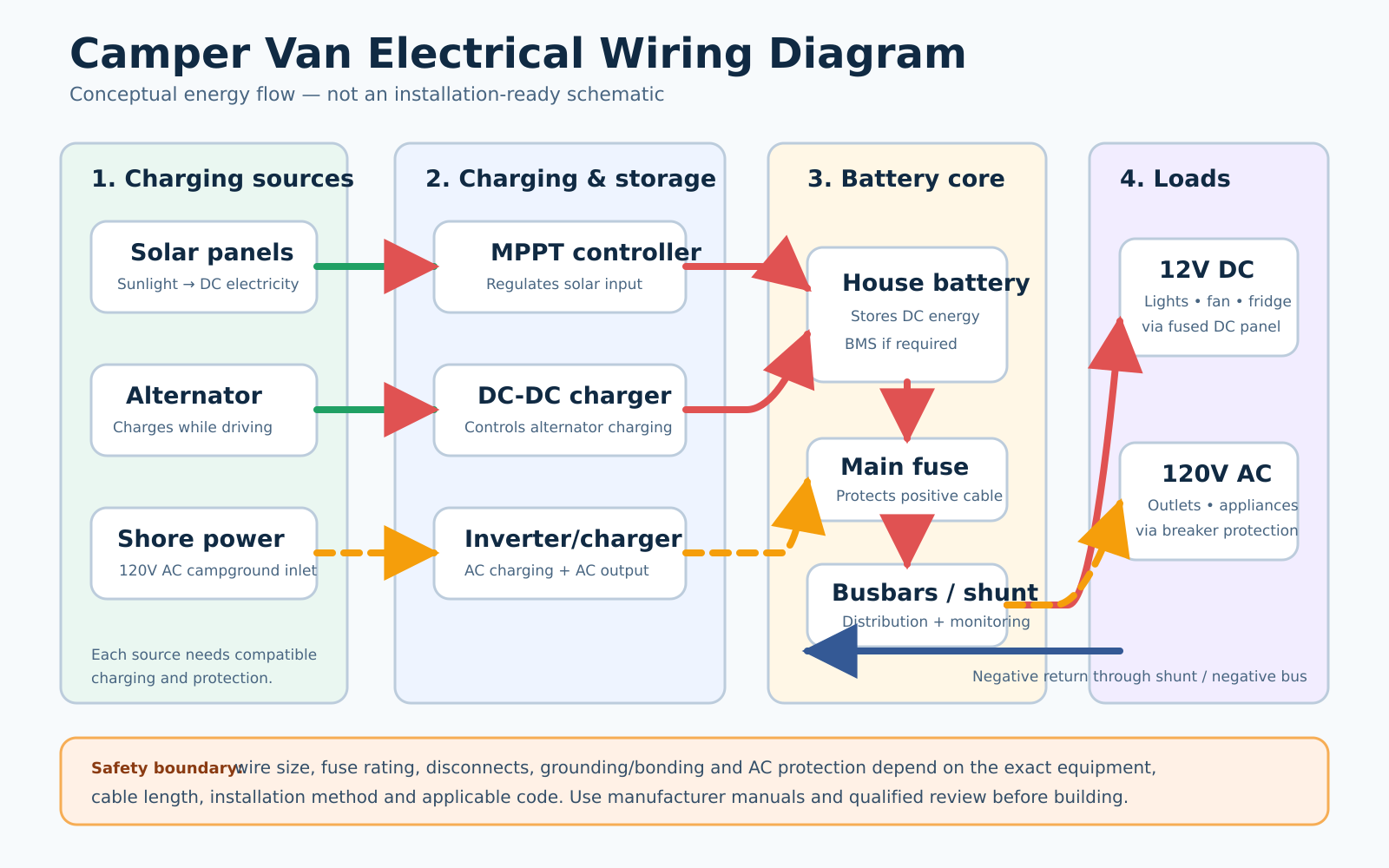
The whole system in six lines
If you only remember one thing from this page, make it this order. Every van system, from a weekend setup to a full-time build, follows it:
- Sources: solar panels, the alternator, shore power.
- Chargers: an MPPT solar controller, a DC-DC charger, an AC battery charger or inverter/charger.
- Protection: fuses or breakers, plus a way to disconnect the battery.
- The house battery (the one your gear lives on, not the engine’s starter battery).
- Distribution: busbars and a fuse panel that split power into separate circuits.
- Loads: lights, fan, fridge and pump on 12V DC; laptop chargers and kitchen gear on 120V AC through an inverter.
How to read any wiring diagram
Pick a source and follow the line until it hits the battery. Then pick a load and follow the line back to the battery. Do that for each source and each load and the drawing stops looking scary.
Two quick checks tell you whether a diagram is any good. First, does every circuit show a negative return path as well as a positive one? A drawing with only positive cables is incomplete, even if the return is “implied.” Second, is it a concept drawing or an installation schematic? A concept drawing shows what connects to what. A real installation schematic also names cable gauges, fuse ratings, terminal locations, equipment models and grounding details. Don’t build from a pretty online illustration that has none of those.
1. Solar charging
Panels → disconnect/fuse where required → MPPT charge controller → fused battery connection
Panels make variable DC power, and the controller turns it into a charging profile your battery can accept. The controller has hard limits on input voltage and current, so you can’t choose panels by wattage alone. Our solar charge controller calculator shows how panel voltage in cold weather and array current affect which controller you need. Your controller’s manual decides what array is allowed.
2. Driving: alternator and DC-DC charger
Starter battery/alternator → input fuse → DC-DC charger → output fuse → house battery
A DC-DC charger controls how much current flows and gives the house battery the right charging profile. That matters most with lithium (see what a LiFePO4 battery is). Simply tying the starter and house batteries together is a common shortcut, and it’s the thing a DC-DC charger is designed to replace. The two batteries are separate energy stores, and a good diagram makes that obvious. Cable size, fuse choice and the ignition-enable wire all depend on the specific charger and vehicle, so follow both manuals.
3. Shore power
Shore inlet → AC protection and distribution → charger or inverter/charger → fused DC connection → house battery
Shore power is AC from a campground pedestal or another outside source. This is where the diagram crosses from AC to DC, so don’t let one line stand in for all of it. Inlet protection, ground-fault protection, neutral-to-ground bonding and transfer switching depend on the equipment and the code. In the US, RV electrical installations fall under standards such as NEC Article 551 and NFPA 1192. This is the part of a build where paying for a qualified professional makes the most sense.
4. Battery, main fuse and disconnect
The house battery is the center of the drawing, because every source and every load meets there through protected wiring. Lithium batteries have a battery management system (BMS) inside or alongside, but the BMS does not replace proper cable protection.
A fuse or breaker exists to protect the wire from too much current. Blue Sea Systems’ technical guidance explains that positive conductors in a DC distribution system generally need circuit protection, with narrow exceptions such as certain engine-starting cables. That’s why protection sits close to the energy source and not near the appliance. A battery disconnect lets you isolate circuits for service or an emergency; its rating and location need to match the system.
5. Busbars
A busbar is a tidy meeting point for several circuits. The positive bar hands out battery power to fused branches, and the negative bar collects the return wires. They keep you from stacking a pile of lugs on the battery terminal. A busbar is not a protective device, though. Each wire leaving it still needs its own fuse, and the bar itself must be rated for the total current it could carry. A cover helps stop a dropped tool from bridging live parts.
6. Battery monitor and shunt
A shunt-based monitor measures current in and out of the battery. In the usual negative-side layout, the battery’s main negative goes to the battery side of the shunt, and every other negative in the system connects to the other side. Any load that bypasses the shunt is invisible to the monitor, which is why the state-of-charge reading drifts. Some batteries and monitors communicate differently, so check both manuals.
7. The 12V DC branch
Battery/main distribution → DC fuse panel → individual fused circuits → switches and loads → negative return
Most lights, pumps, roof fans, USB outlets and many fridges run on 12V DC. Each circuit is sized for its expected current, its wire length, how much voltage drop is acceptable, the insulation rating and how it’s routed. The wire fuse must protect the wire, and the appliance maker may also set a lower maximum. That’s why a rule like “use this wire and this fuse for every fridge” is unsafe. Run the numbers in the wire gauge calculator for your actual load and distance.
8. Inverter and 120V AC
An inverter turns battery DC into household-style AC. Big inverters pull very high DC current, which is why they get short, heavy battery cables, their own fuse and disconnect, and room to breathe. Not sure what size you need? Our camper van inverter guide covers continuous watts, surge and idle draw. AC output should feed properly designed AC distribution, not an improvised extension of household wiring. An inverter/charger can also pass shore power through and charge the battery, but transfer and bonding behavior varies by model, so follow the maker’s schematic.
Where DIY diagrams go wrong
- Copying a diagram because the part names look similar. Two inverters with the same watt rating can need different cables, fuses and bonding.
- Forgetting the negative side. The return path is half the circuit.
- Putting the fuse far from the source. Protection belongs close to where the power comes from.
- Bypassing the shunt. The battery monitor then reports numbers that don’t match reality.
- Tying starter and house batteries together without a controlled charging device.
- Sizing a solar controller by watts only. Voltage and current limits matter just as much.
- Raising a fuse to stop it blowing. That leaves the wire under-protected. Find out why it’s blowing instead.
- Mixing up “ground,” “negative” and “neutral.” They do different jobs, and AC bonding can change between shore and inverter modes. Don’t guess; use the inverter/charger manual and have the design checked.
Check your diagram before you buy parts
- Are all charging sources and their controllers shown?
- Does every circuit have both a positive and a negative path?
- Is there a fuse or breaker close to each source and on every branch?
- Are cables, lugs, busbars and fuse holders rated for the current they’ll carry?
- Does the battery chemistry match the charger profile?
- Does all monitored current pass through the shunt?
- Are DC and AC kept clearly separate?
- Is the shore inlet, transfer and ground-fault setup fully documented?
- Has every part been checked against its own manual and the applicable code?
Want to test a design before you spend anything? The power system simulator shows how a day of appliance use, sun and battery size play out.
Quick answers
Do solar, alternator and shore power all connect straight to the battery?
Not directly. Each goes through its own charging equipment and protection first. The connection point is often a fused busbar rather than the battery terminal itself.
Can I copy a wiring diagram from the internet?
Use it to learn how a system is organized, not as an installation spec. Your gear, wire runs, vehicle and local rules can all call for something different.
Does the fuse protect the appliance or the wire?
Mainly the wire. The appliance’s manual may add a lower maximum fuse rating, and you should follow both.
Should a beginner wire the 120V AC side?
Get a qualified person to design or review it. AC faults can cause shock and fire, and the rules differ by installation.
The takeaway
Trace one path at a time: source, charger, battery, protection, distribution, load. The drawing shows how the pieces relate. Your manuals, your calculations, the code and a professional check are what turn those relationships into a safe installation.
Sources and further reading: Victron Energy Van/Motorhome Manual & Drawing; Blue Sea Systems: DC Circuit Protection; Blue Sea Systems: DC Main Power Distribution; Blue Sea Systems: Selecting a Fuse and Fuse Holder; RV Industry Association: NEC Articles 551 and 552.
Last updated: October 6, 2026. This is general educational information. It does not replace manufacturer instructions, electrical code requirements or advice from a qualified electrician.