
A camper van electrical wiring diagram is a map of how energy enters, moves through, and leaves a van’s electrical system. At first glance, the lines and symbols can look overwhelming. The easiest way to read the diagram is to stop treating it as one giant circuit and divide it into four sections: charging sources, charging equipment, battery storage and power distribution.
This guide explains that flow in plain language. It builds on our beginner’s guide to van electrical systems, but it does not provide installation-ready wire sizes or fuse ratings. Those details must be calculated for the actual equipment, cable length, installation method and applicable electrical standards.
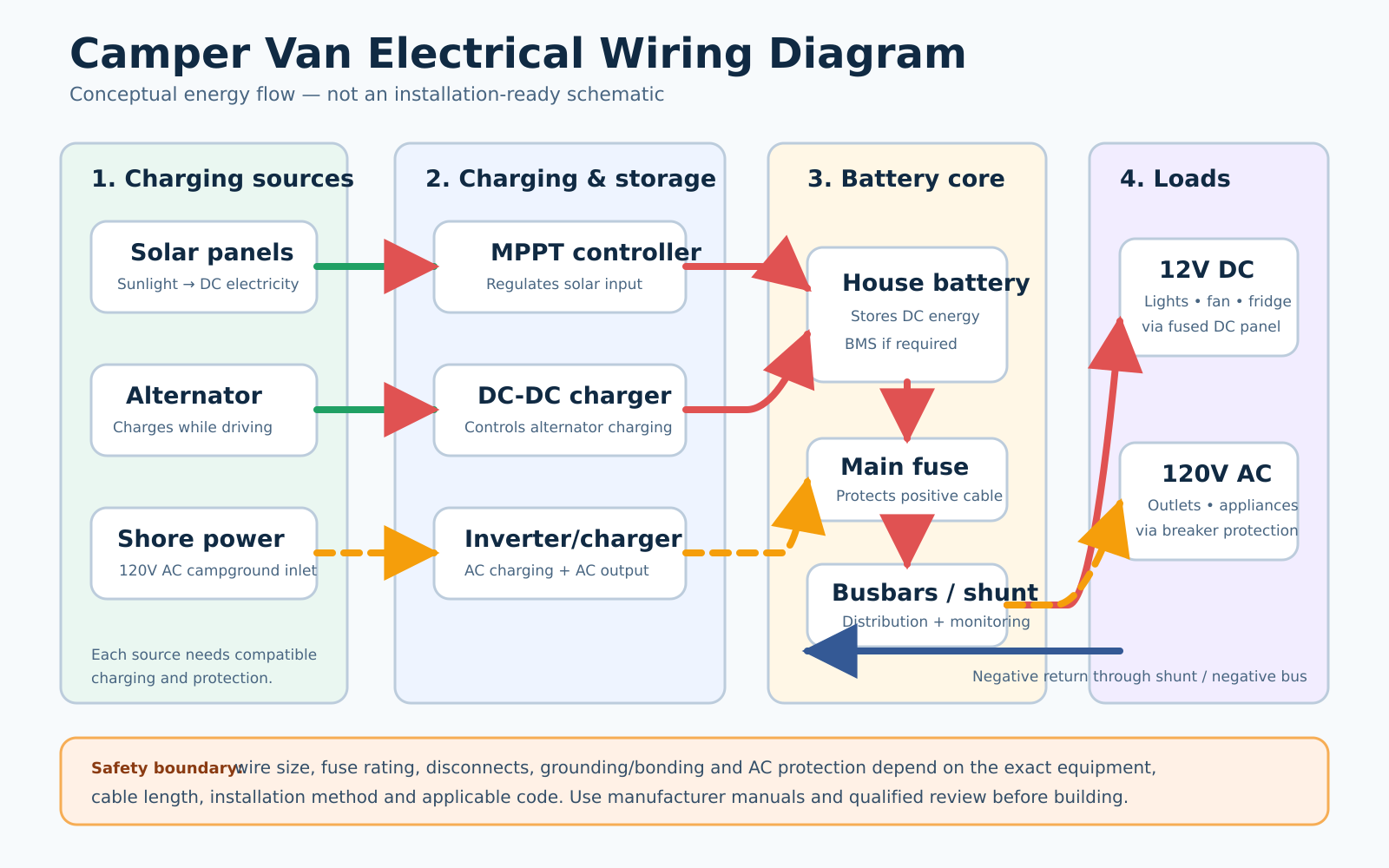
How to Read a Camper Van Electrical Wiring Diagram
Begin at an energy source and follow the line toward the load. In a typical diagram, solar panels, the vehicle alternator and shore power are the three possible sources. Each source passes through equipment that controls or converts the incoming power before it reaches the house battery.
From the battery, power normally passes through circuit protection and distribution equipment before reaching lights, fans, refrigerators, outlets or other loads. The negative side must also have a complete return path. A diagram that shows only positive cables is incomplete, even if the negative return is implied.
Conceptual diagram vs. installation schematic
When reading any camper van electrical wiring diagram, first decide whether it is conceptual or installation-ready. A conceptual diagram tells you what connects to what. An installation schematic should also identify cable gauges, fuse or breaker ratings, terminal locations, disconnects, conductor lengths, equipment model numbers and grounding or bonding details. Never assume that a clean online illustration contains enough information to build safely.
1. Solar Charging Branch
The solar branch normally follows this path:
Solar panels → solar disconnect/protection as required → MPPT charge controller → protected battery connection
Panels generate variable DC power. A compatible solar charge controller regulates that input into a charging profile the house battery can use. Controller limits include maximum photovoltaic voltage and current, so panel configuration cannot be chosen from wattage alone. The controller’s manual should determine the permitted array and the required protection.
If you are planning this branch, see our Solar Power guides for the concepts that should be understood before selecting components.
2. Alternator and DC-DC Charging Branch
The driving-charge branch commonly appears as:
Starter battery/alternator → input protection → DC-DC charger → output protection → house battery system
A DC-DC charger controls current and applies an appropriate charging profile instead of simply connecting the starter and house batteries together. This is particularly important when battery chemistry or vehicle charging behavior differs. Compatibility, cable size, fuse selection and enable/ignition wiring depend on the charger and vehicle, so the device manual and vehicle guidance are the controlling references.
The starter battery and house battery are separate energy stores. A well-designed diagram makes that separation obvious and shows how each side of the charger is protected.
3. Shore-Power Charging Branch
Shore power is alternating current supplied from a campground pedestal or another external source. It may feed a standalone battery charger or an inverter/charger. A simplified flow is:
Shore inlet → required AC protection/distribution → charger or inverter/charger → protected DC connection → house battery
This part of the system crosses from AC to DC and should not be reduced to a single unexplained line. Inlet protection, overcurrent protection, ground-fault protection, neutral-to-ground bonding behavior and transfer switching are code- and equipment-dependent. In the United States, recreational-vehicle electrical installations are addressed by standards including NEC Article 551 and NFPA 1192. Use a qualified professional for the AC design and installation.
4. House Battery, Main Fuse and Disconnect
The house battery is the center of the diagram because charging sources and loads meet there through protected distribution. Depending on battery chemistry, the bank may include an internal or external battery management system (BMS). The BMS is important, but it is not a replacement for correctly selected cable protection.
A fuse or circuit breaker protects a conductor against excessive current. Blue Sea Systems’ technical guidance explains that positive conductors in a DC main distribution system generally require circuit protection, with limited exceptions such as specific engine-starting conductors. Protection is therefore shown close to the energy source—not near the appliance merely for convenience.
A battery disconnect provides a way to isolate selected circuits for service or emergencies. Its location and rating must match the intended current and system architecture.
5. Positive and Negative Busbars
Busbars are organized connection points for multiple circuits. A positive busbar distributes battery power to protected branches, while a negative busbar gathers return conductors. They help avoid unsafe stacks of cable lugs directly on battery terminals.
Busbars are not automatically protective devices. Each conductor still needs appropriate overcurrent protection, and every busbar must be rated for the maximum current it may carry. Covers and suitable enclosures help prevent tools or loose conductive objects from bridging energized parts.
6. Battery Monitor and Shunt
A shunt-based battery monitor measures current flowing into and out of the house battery. In a typical negative-side arrangement, the battery’s main negative terminal connects to the battery side of the shunt, while system negative connections go to the load/system side. If a load bypasses the shunt, the monitor cannot count that current accurately.
Some systems use battery communication or different monitoring arrangements, so the battery and monitor manuals remain authoritative.
7. The 12-Volt DC Load Branch
Most van lights, water pumps, roof fans, USB outlets and some refrigerators are DC loads. Their branch often reads:
House battery/main distribution → DC fuse panel → individual fused circuits → switches and loads → negative return
Each branch circuit should be sized for its expected current, conductor length, allowable voltage drop, insulation rating, ambient conditions and routing method. The fuse must protect the wire, while the equipment manufacturer may specify a lower maximum fuse rating. That is why a universal statement such as “use this wire and this fuse for every fridge” is unsafe.
For more battery-side concepts, visit our Batteries & 12V section.
8. Inverter and 120-Volt AC Loads
An inverter converts house-battery DC into AC for compatible appliances. High-power inverters can draw very high DC current, which is why their short battery cables, protection, disconnects, ventilation and terminal torque deserve special attention.
The AC output should feed properly designed AC distribution and protection—not an improvised extension of household wiring. An inverter/charger may also transfer shore power and charge the battery, but transfer and bonding behavior varies by model. Follow the exact manufacturer schematic and applicable code.
Why the Diagram Does Not Show Universal Wire or Fuse Sizes
Wire and fuse selection is a calculation, not a decorative label. At minimum, the designer needs to know:
- maximum continuous and surge current;
- one-way or round-trip conductor length, as required by the method;
- system voltage and acceptable voltage drop;
- wire insulation temperature rating and whether conductors are bundled;
- ambient temperature and routing conditions;
- terminal, fuse holder and equipment ratings;
- the manufacturer’s required or maximum protection value; and
- the electrical standard that applies to the installation.
A fuse is selected to protect the conductor and must also fit within equipment requirements. Increasing a fuse rating to stop nuisance blowing can leave the cable under-protected.
Grounding and Bonding: Do Not Guess From a Simple Diagram
“Ground,” “negative” and “neutral” are not interchangeable labels. The vehicle chassis may be part of a DC return arrangement, while the AC equipment-grounding conductor serves a different safety function. Neutral-to-ground bonding may change depending on shore-power or inverter operating mode. A conceptual diagram cannot safely specify these details for every vehicle and inverter/charger.
Use the inverter/charger manual, the vehicle manufacturer’s guidance and the applicable RV electrical code. This is one of the strongest reasons to have the finished schematic inspected before energizing it.
Camper Van Wiring Diagram Review Checklist
Before turning a camper van electrical wiring diagram into a parts list or installation plan, review every branch against the following checks.
- Are all charging sources and their controllers shown?
- Does every circuit have a complete positive and negative path?
- Is protection shown close to each energy source where required?
- Are cables, terminals, busbars, switches and fuse holders rated for expected current?
- Are battery chemistry and charger profiles compatible?
- Does all monitored current pass through the shunt?
- Are DC and AC distribution clearly separated?
- Are shore inlet, transfer, ground-fault and breaker arrangements fully documented?
- Are conductor sizes based on current, length, voltage drop and installation conditions?
- Has the final design been checked against every manufacturer manual and applicable code?
Common Diagram-Reading Mistakes
The most common mistake is copying a diagram because the component names look similar. Two inverters with the same power rating can have different terminal, fuse, cable, bonding and transfer requirements. Other errors include ignoring the negative return, placing protection far from the source, bypassing a monitoring shunt, mixing starter and house-battery circuits without a controlled charging device, and treating a solar controller’s watt rating as its only limit.
A diagram should be the beginning of the engineering process, not proof that a system is safe.
Frequently Asked Questions
What is the basic order of a camper van electrical system?
Charging sources feed compatible charge controllers or chargers, which feed the house-battery system. Protected DC distribution supplies 12V loads, while an inverter and protected AC distribution supply compatible AC loads.
Do solar, alternator and shore charging all connect directly to the battery?
They normally reach the battery system through compatible charging equipment and required protection. The exact connection point may be a protected busbar or distribution system rather than the battery terminal itself.
Can I copy a camper van wiring diagram from the internet?
Use it to learn system architecture, not as an installation specification. Your equipment, cable runs, vehicle, loads and applicable standards can require different wiring and protection.
Does the fuse protect the appliance or the wire?
The primary purpose of overcurrent protection is to protect the conductor from excessive current. Equipment instructions may also impose a lower maximum fuse rating that must be followed.
Should a beginner install the 120V AC system?
AC faults can cause shock, fire or electrocution. A qualified professional should design or review the AC system and verify it against applicable RV electrical requirements before use.
Final Takeaway
A camper van electrical wiring diagram becomes easier to understand when you trace one path at a time: source, charger, house battery, protection, distribution and load. The diagram explains the relationships; manufacturer manuals, calculations, codes and professional review turn those relationships into a safe installation.
Sources and further reading: Victron Energy Van/Motorhome Manual & Drawing; Blue Sea Systems: DC Circuit Protection; Blue Sea Systems: DC Main Power Distribution; Blue Sea Systems: Selecting a Fuse and Fuse Holder; RV Industry Association: NEC Articles 551 and 552.
Last technically reviewed: September 1, 2026. This educational article does not replace manufacturer instructions, code requirements or professional electrical advice.
Continue learning in our Van & RV Electrical guides.
A camper van electrical wiring diagram is a planning document that must be verified against exact equipment manuals, protection requirements, and applicable standards.