
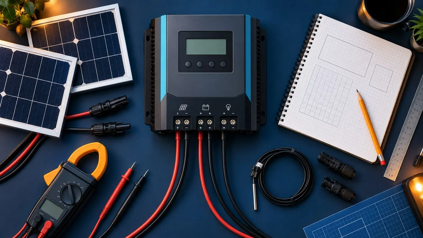
This solar charge controller calculator provides a screening estimate for MPPT current, array power, and voltage; final selection must satisfy the exact controller manual.
What this calculator does
This solar charge controller calculator estimates required output current and checks the array information needed for an MPPT controller. It is a screening tool, not final approval. The controller manufacturer’s sizing calculator and current manual must confirm the exact module, series/parallel layout, temperature range, battery voltage, wire, fuse, and allowed oversizing.
Four limits must be checked separately:
- Maximum PV open-circuit voltage at the coldest expected condition.
- Maximum PV short-circuit current for parallel strings.
- Maximum controller output current into the battery.
- Maximum permitted array wattage at the selected battery voltage.
Passing one limit does not imply the others pass.
Required inputs
From the solar-module datasheet:
- maximum power, Pmax, in watts;
- open-circuit voltage, Voc;
- voltage at maximum power, Vmp;
- short-circuit current, Isc;
- current at maximum power, Imp;
- Voc temperature coefficient and its units; and
- maximum series-fuse rating.
From the design:
- panels in series per string;
- number of parallel strings;
- coldest expected module or ambient temperature, as required by the method;
- nominal battery voltage and maximum charge voltage;
- battery maximum charge current; and
- simultaneous output of other chargers.
From the controller manual:
- absolute maximum PV Voc;
- allowed PV short-circuit current;
- MPPT operating range and start requirement;
- rated output current;
- maximum PV power by battery voltage; and
- documented array-oversizing policy.
Calculator 1: array nameplate power
Array watts = panel watts x total number of panels
Example: four 200W modules create an 800W nameplate array.
Nameplate power is measured under standard test conditions. It does not mean the array will produce 800W throughout the day. Temperature, irradiance, angle, shade, dirt, wiring, and controller limits change actual power.
Calculator 2: estimated controller output current
A simple current screen is:
Estimated charge amps = array watts / battery charging voltage
Using charging voltage gives a more realistic output-current estimate than nominal battery voltage. For an 800W array charging a 12V LiFePO4 bank at 14.4V:
800 / 14.4 = 55.6A
Allowing for conversion efficiency would reduce expected current, but do not use that reduction to select a smaller controller unless the manufacturer directs it. A 60A controller is the first class to evaluate, subject to its PV power, voltage, and current limits.
For a 24V bank charging at 28.8V:
800 / 28.8 = 27.8A
This illustrates why the same solar array requires less battery-side current at higher system voltage.
Calculator 3: series voltage
At the datasheet test condition:
String Voc = panel Voc x panels in series
String Vmp = panel Vmp x panels in series
If a panel has Voc 24.0V and Vmp 20.0V, three in series produce 72.0V Voc and 60.0V Vmp at the reference condition. That is not the final voltage check because Voc rises in cold conditions.
Calculator 4: cold-corrected Voc
If the datasheet gives a negative Voc coefficient as percent per °C, a simplified correction below the 25°C reference is:
Corrected panel Voc = rated Voc x [1 + (absolute coefficient x temperature difference)]
Example inputs:
- Rated Voc: 24.0V
- Voc coefficient: -0.28%/°C
- Reference: 25°C
- Cold condition: -10°C
- Difference: 35°C
Convert 0.28 percent to 0.0028:
24.0 x [1 + (0.0028 x 35)] = 26.35V
For three panels in series:
26.35 x 3 = 79.05V
This string exceeds a 75V controller and may fit a 100V controller only after the manufacturer-required tolerances and margin are included. Do not design exactly to an absolute maximum.
Some datasheets express coefficients in volts per °C rather than percent per °C, and some controller tools use cell temperature instead of ambient temperature. Follow the stated units. Victron and MidNite Solar provide official tools that handle product-specific details more reliably than a generic formula.
Calculator 5: parallel current
For identical strings in parallel:
Array Isc = panel Isc x parallel strings
Array Imp = panel Imp x parallel strings
If each string has Isc 11.5A and two strings are paralleled, total Isc is 23A at the datasheet condition. Apply the controller manufacturer’s required current factor and compare with its maximum PV short-circuit current.
Series panels do not add current; parallel strings do not add voltage. Mixed orientations, shade, or unequal modules can complicate the result. Do not mix electrical characteristics on one tracker without manufacturer support.
Sizing worksheet
| Check | Formula or source | Result |
| Total panels | series x parallel | ___ |
| Array watts | panel W x total panels | ___ W |
| STC string Voc | panel Voc x series | ___ V |
| Cold-corrected string Voc | corrected Voc x series | ___ V |
| String Vmp | panel Vmp x series | ___ V |
| Total Isc | panel Isc x parallel | ___ A |
| Total Imp | panel Imp x parallel | ___ A |
| Estimated output | array W / charge V | ___ A |
| Controller PV power limit | manual | ___ W |
| Battery charge-current limit | battery manual | ___ A |
If any result is blank, the system is not ready for final selection.
Worked example: 400W on a 12V battery
Assume two identical 200W modules with:
- Voc 24.0V;
- Vmp 20.0V;
- Isc 10.8A;
- Imp 10.0A; and
- Voc coefficient -0.28%/°C.
The design uses two panels in series, one string, with -10°C as the selected cold condition.
Array power is 400W. Corrected panel Voc is 26.35V, so the string is approximately 52.7V. String Vmp at the datasheet condition is 40V. Array Isc is 10.8A. Estimated output at 14.4V is 27.8A.
A 100/30-style controller may appear suitable by the headline numbers: corrected Voc below 100V and output near 30A. The final check must confirm the exact controller’s PV Isc limit, allowed 400W input at 12V, start voltage, temperature method, and oversizing policy. Also confirm that 30A is acceptable to the battery.
Worked example: 800W on a 24V battery
Use four of the same 200W panels as two in series and two parallel strings.
- Array power: 800W.
- Cold-corrected string Voc: about 52.7V.
- String Vmp: 40V.
- Total Isc: 21.6A before any required factor.
- Estimated output at 28.8V: 27.8A.
The voltage is unchanged from the first example because series count is unchanged. Current doubles because there are two parallel strings. A controller with adequate output amps can still fail if its PV short-circuit-current limit is below the corrected array result.
MPPT operating voltage
The array must be high enough above battery voltage for the controller to start and track. Victron’s EasySolar-II GX guidance, for example, states product-specific requirements for PV voltage relative to battery voltage. Those numbers belong to that product, not every controller.
A single so-called 12V panel may have Vmp around 18–20V and work with a 12V bank, while it may not provide adequate operating voltage for a 24V bank. The controller cannot create usable energy when the array voltage is outside its operating window.
Array oversizing
Some MPPT manufacturers permit array wattage above the controller’s nominal output power. The controller clips power at its current limit during the strongest conditions while harvesting more energy in weak sun. Victron has documented up to 130 percent oversizing in its calculator context, while other manufacturers use different limits.
Oversizing never permits exceeding absolute PV voltage or current limits. It can also increase the time a controller operates at maximum output, raising thermal and cable demands. Use only the current policy for the exact controller.
Battery charge-current coordination
Add the maximum output of every charger that can operate together:
Combined charge current = solar controller + DC-to-DC charger + shore charger + other sources
If the battery bank accepts a maximum 100A and the alternator charger can supply 50A, a 60A solar controller could exceed the limit when both operate. Reduce programmed limits, coordinate through a BMS or control system, or redesign the sources.
Cable and fuse checks
The calculator does not select cable and fuses automatically. Use the controller manual, conductor ampacity, ambient and bundle adjustments, voltage drop, terminal ratings, and applicable standards. Battery-side protection must have adequate interrupt capacity for the bank. PV-side fusing depends on parallel-string fault current, module maximum series-fuse rating, and system layout.
Place protection near the power source as required, support cables against vibration and abrasion, and use DC-rated disconnects. Verify torque using the equipment manual.
Selection checklist
- Exact module datasheet, including temperature coefficients.
- Coldest credible temperature for the installation.
- Correct series and parallel calculations.
- Margin below the controller’s absolute PV voltage.
- Total Isc inside the product’s PV-current limit.
- Array watts inside the documented limit or oversizing policy.
- Controller amps inside battery charge limits.
- Combined chargers coordinated.
- MPPT start and operating voltage satisfied.
- Cable, fuse, disconnect, and connector design complete.
Final recommendation
Use this page to reject obviously incompatible combinations, then run the exact array through the controller manufacturer’s official sizing tool. Save the input datasheets and result with the system record. When the calculation sits close to a voltage, current, temperature, or battery limit, choose more margin or obtain a qualified design review rather than assuming the controller will protect itself.
Sources
- Victron Energy MPPT Calculator
- Victron Energy: Solar Charge Controllers
- Victron Energy: PV Array Design
- Renogy: Solar Charge Controller Sizing
- MidNite Solar Classic Sizing Tool
- U.S. Department of Energy: PV Performance and Efficiency
Frequently asked controller-sizing questions
Can controller amps be calculated as panel watts divided by 12?
That is a rough screen for a 12V-class bank, but actual charging voltage is higher and controller efficiency matters. Use array watts divided by the battery charging voltage for a better estimate, then follow the manufacturer’s sizing rule. PV voltage, PV current, and permitted array wattage still require separate checks.
Should the result be rounded up?
Move to a standard controller rating that satisfies output current and the manufacturer’s oversizing policy. Do not round a 96V cold Voc into a 100V controller without required margin and tolerance. Voltage is an absolute limit, not a convenient size class.
What changes when panels are placed in series?
String Voc and Vmp rise with each panel while current stays approximately the same. This can reduce cable loss and help MPPT operation, but cold voltage may exceed the controller. Shading on one module may affect the string depending on bypass diodes and conditions.
What changes when strings are placed in parallel?
Current adds while voltage stays approximately the same. The controller’s PV current limit, conductor size, connectors, combiner, and possible string fusing become more demanding. Parallel wiring does not solve a minimum-operating-voltage problem.
Can a larger controller damage the battery?
It can if maximum output is not limited to what the battery accepts. Many controllers allow a programmable current limit, but settings can reset or another charger can operate simultaneously. Coordinate total charge current and BMS control.
Why does the official calculator recommend a different model?
It may account for temperature coefficients, product-specific start voltage, power derating, current limits, and oversizing rules that a generic formula omits. Review its inputs and use the official recommendation unless the manufacturer confirms another design.
Controller comparison record
When two models pass the basic electrical checks, compare operating-temperature derating, conversion efficiency, idle consumption, cooling, enclosure rating, communication, remote enable, temperature sensor support, programmable lithium settings, data logging, warranty, and local service. A larger amp rating alone may not improve energy harvest if array watts and battery acceptance are unchanged.
Commissioning measurements
Record PV open-circuit voltage before connection only under the safe procedure, operating PV voltage/current, battery voltage/current, controller temperature, and active limits. Compare readings with irradiance and temperature rather than expecting nameplate power. Test charger shutdown from the BMS or remote enable, confirm equalization is disabled for LiFePO4, and verify combined charge current with other sources.
Inspect terminals after a sustained high-output period using safe methods. Unexpected temperature rise can indicate undersized cable, a loose crimp, incorrect torque, or a holder/connector rating problem even when controller current appears normal.
Assumptions to publish beside an online calculator
An interactive calculator should display the reference temperature, coefficient units, whether the user enters ambient or cell temperature, formula used for cold correction, whether current factors are applied, assumed charge voltage, whether efficiency affects output current, and the fact that official manufacturer limits prevail. Provide the intermediate results so a reader can spot a wrong sign or unit instead of receiving one unexplained model number.
Update policy for the calculator
Review controller examples whenever a manufacturer changes a manual, firmware, or product generation. Keep formulas separate from product limits so a model update does not silently alter the arithmetic. Display a “last verified” date beside each controller profile and preserve the source URL.
If the calculator is later automated, validate it against several official manufacturer-tool results, including a cold-voltage failure, a parallel-current failure, a battery charge-current failure, and a valid case. Publish those test inputs and expected outcomes so future changes can be checked.
A useful result page should show why a controller fails: cold voltage, array current, output current, power, or operating window. Specific failure messages help the reader change series/parallel layout intelligently instead of moving to a larger controller without understanding the constraint.
Keep one manual calculation with the saved result. It provides a transparent cross-check if the web tool, firmware, or controller database later changes.