
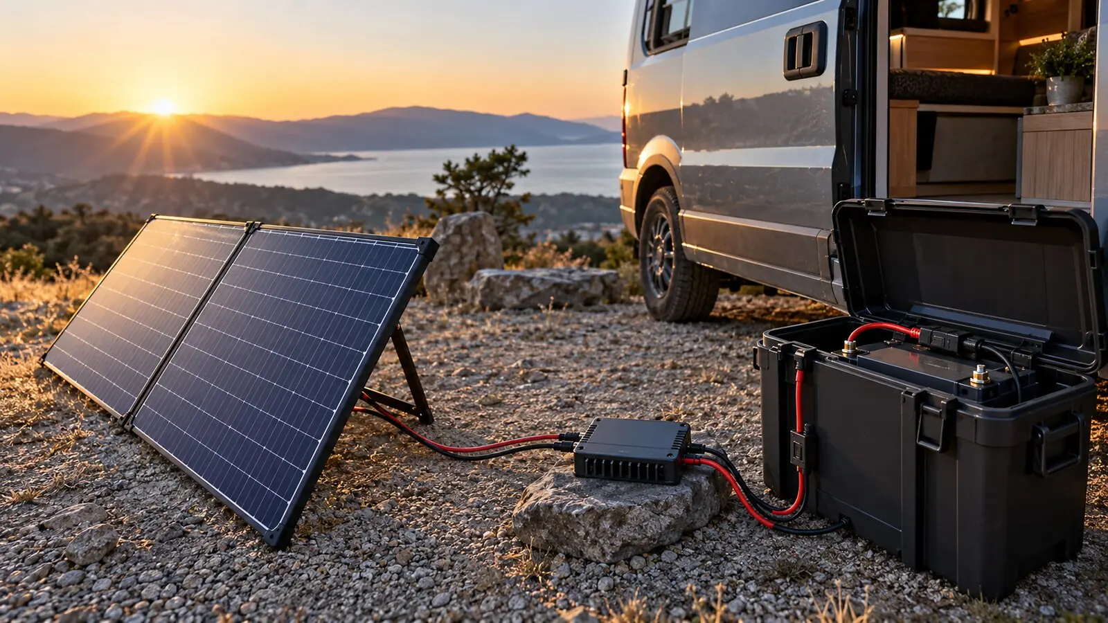
To charge a LiFePO4 battery from solar, you need three things working together: panels, a solar charge controller, and a battery with the right charge settings. The panels never connect straight to the battery. They go through a correctly sized controller, which is set up for your exact battery and wired with the cable, fuse and connection order the manuals specify.
The wiring diagram is the easy part. The hard part is proving the panels stay inside the controller’s voltage limits on a freezing, sunny morning, that the controller’s output suits the battery, and that every charging source switches off when the battery is too cold. This guide walks through it in nine steps.
Quick summary: Use an MPPT solar charge controller sized for cold-weather panel Voc, program the lithium profile to your battery manual’s exact bulk/absorption voltage (for example, 14.4V for Battle Born 12V banks), turn off equalization, and ensure low-temperature charge protection blocks charging below 32°F (0°C) unless your battery includes controlled self-heating.
The four parts
Panels (the array)
Panels make DC power that rises and falls with sun, temperature and how they’re wired. The label values (Voc, Vmp, Isc, Imp) are measured under lab test conditions, not what you’ll see on a typical day. Panels in series add voltage; panels in parallel add current. Series wiring cuts current and cable loss, but it also pushes the string’s voltage closer to the controller’s maximum. Panel voltage rises as cells get colder, so size it with the panel’s temperature coefficient and the lowest temperature you’ll see, or use the controller maker’s official sizing tool.
Solar charge controller
An MPPT controller can take a higher panel voltage and convert it down to battery voltage while tracking the array’s best power point. A PWM controller is simpler and can work for small, well-matched systems, but harvest may be lower in some conditions. A controller has several separate limits: maximum PV open-circuit voltage, maximum PV short-circuit current, maximum charge current, maximum array power at your battery voltage, and a minimum PV voltage to start working. Your array has to pass every one, not just the wattage line.
Battery and BMS
The battery stores the energy, and the BMS protects the cells from over-voltage, under-voltage, too much current and bad temperatures. The BMS doesn’t replace correct controller settings. If it disconnects the battery while the controller is running, the rest of the system must stay within what the equipment makers allow.
Protection and monitoring
The controller-to-battery cable normally needs a fuse or breaker near the battery, sized to protect the cable and match the controller manual. Panel-side fusing depends on string count, the panel’s maximum series-fuse rating and the applicable rules. Any disconnect must be rated for DC at your voltage and current. A shunt-based battery monitor tells you far more than voltage can across LiFePO4’s flat middle range.
Step 1: Work out how much energy you use each day
List every load in watt-hours per day. Measure variable loads like fridges over a typical period, and add inverter idle draw, conversion losses and small always-on devices.
Say your loads total 1,200 Wh and you get about four equivalent peak-sun hours. That’s 1,200 ÷ 4 = 300 W of panels in theory. Add a 25% allowance for heat, angle, dirt, wiring and imperfect conditions: 300 ÷ 0.75 = 400 W. Treat that as a planning number, not a promise. A shaded van roof can produce far less, and short winter days can drive the whole design. Alternator or shore charging may cover the gap more reliably. Our power system simulator lets you try sunny, cloudy and no-solar days.
Step 2: Get the battery’s charge limits from its manual
Open the current manual and write down:
- recommended and maximum charge current;
- bulk/absorption voltage and absorption time;
- float requirement or accepted range;
- low- and high-temperature charging limits;
- any BMS communication or remote-disable requirement;
- approved series and parallel layouts.
Don’t borrow settings from another brand. Battle Born, for example, recommends 14.4V bulk/absorption for its 12V batteries, while other makers publish a range. Your battery’s own manual wins.
Step 3: Size the controller’s output current
A quick first estimate for an MPPT controller is array watts ÷ nominal battery voltage. A 400 W array on a 12V battery gives 400 ÷ 12 = 33.3 A, so compare controllers around 40 A. On a 24V bank the same array makes roughly half the current. Check the manual before adding any safety factor: some controllers allow controlled oversizing of the panels and simply clip output at the current limit, while others specify different limits. The panel voltage and short-circuit current checks still apply even when output power is clipped.
Step 4: Check panel voltage at the coldest temperature
The controller maker’s sizing calculator (Victron’s MPPT calculator is a good example) is the best tool. It asks for the panel’s Voc, Vmp, Isc, Imp, temperature coefficients, how many panels in series and parallel, and your lowest expected temperature. Or try our solar charge controller calculator for a screening estimate.
Here’s the idea with example numbers. A panel has a Voc of 24.0V at 25°C and a Voc temperature coefficient of -0.28% per °C. At -10°C that’s 35°C colder than the test condition:
24.0 × (1 + 0.0028 × 35) = 26.35 V per panel
Three of those in series is about 79.1 V before any extra tolerance, so a 75 V controller fails the check. The final numbers must come from your panel and controller manuals, because sign conventions and reference conditions differ.
Step 5: Check panel current and power
Parallel strings add short-circuit current. Compare the total, corrected, with the controller’s maximum PV short-circuit current and any design factor it asks for. Also check the panel’s maximum series-fuse rating, because parallel strings can send reverse current that exceeds it and may need string fuses. And confirm how much PV power the controller allows at your actual battery voltage. Renogy’s Rover 40A page, for instance, lists different maximum PV power for 12V and 24V systems, which is why amps alone don’t tell you enough.
Step 6: Size the battery-side cable and fuse
Start with the controller manual’s cable and fuse recommendations. Then check voltage drop over the full positive and negative run, and the cable’s current rating for the insulation, heat, bundling and terminals. For a quick estimate, use our 12V wire gauge chart or the wire gauge calculator. Then choose a fuse that protects the wire without exceeding the equipment’s limits; the fuse sizing calculator helps as a starting point. Put battery-side protection close to the battery, and use DC-rated parts with enough interrupt capacity. LiFePO4 can deliver a very high fault current.
Step 7: Program the controller
Pick or create the lithium profile, then check every value. Don’t assume a preset matches your battery. Switch off equalization and lead-acid temperature compensation unless the battery maker permits them.
Also set the maximum charge current so that all your chargers together stay within the battery’s limit. A 50 A solar controller and a 40 A DC-DC charger running at the same time can put close to 90 A into the bank before any loads. Coordinate them through settings or the BMS if needed.
Step 8: Block charging in the cold
Many LiFePO4 batteries must not be charged below 32°F (0°C), though the exact limit varies. Protection can live in the battery, come through a BMS signal, or be done by the charger with a suitable sensor. It has to shut off solar, alternator and shore charging, not just one. A self-heating battery may use incoming solar to warm its cells first, so check how it behaves in weak morning sun and whether the controller recovers after a low-temperature or low-voltage disconnect.
Step 9: Connect in the right order
Many controller manuals say to connect the battery before the panels so the controller can detect system voltage. Others differ, so follow your manual. A typical sequence:
- Check polarity, torque and cable support, with disconnects open.
- Connect the temperature/BMS control and battery-side protection.
- Connect or enable the controller at the battery.
- Confirm it identifies the right battery voltage and profile.
- Connect or enable the panel input.
- Watch voltage, current, temperature and charge state.
Shut down using the manufacturer’s stated order.
Check it works
On a clear day, compare the panels’ real voltage and current with the conditions instead of expecting nameplate power. Make sure the controller never exceeds the battery current or voltage you programmed. Check terminal temperatures during a long charge, using safe methods. Don’t tighten energized terminals casually. Test how the system responds when the battery is full, when a big load starts, when the temperature cutoff is active, and when the BMS disables charging. Write down final settings, firmware versions, panel layout, fuse types and cable sizes.
If charging is low
- Panel voltage but no charge: the battery may be full, panel voltage may sit too close to battery voltage, a disconnect may be open, or the BMS may be blocking charge.
- Less current than expected: look at shade, sun angle, panel temperature, dirt, connector loss, the controller’s current limit, battery acceptance, running loads and the panel layout.
- Over-voltage error: disconnect per the manual and re-check the cold-corrected series Voc. Don’t keep resetting it.
- BMS cuts off near full: check charge voltage, absorption time, cell balance and wiring voltage drop, and follow the battery maker’s support advice rather than raising limits.
The takeaway
Treat solar charging as one system, not three products with matching connectors. Size the energy first, pass the controller’s voltage and current limits at the extremes, then program the battery’s exact profile and cold-weather protection. If the design has high current, several charging sources, unfamiliar roof wiring or a living space involved, get it reviewed by a qualified installer.
Sources: Victron Energy MPPT Calculator; Victron Energy: PV array design; Renogy: Solar Charge Controller Sizing; Renogy Rover Li 40A specifications; Battle Born Batteries: Charging LiFePO4 Batteries; Victron Energy: Wiring Unlimited.
Related guides: LiFePO4 battery charger guide, solar charge controller calculator, best portable solar panels for camping.
Last updated: October 6, 2026. General educational information. Always follow your panel, controller and battery manuals, and use a qualified installer for high-current or complex systems.